Multiplex Jr.
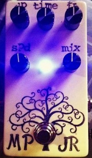
1776 Effects Multiplex Jr pedal. This pedal is an earlier and stripped-down version of the Multiplex Echo Machine, also by 1776. Unlike the Multiplex echo machine, only offers an emulation of the Echoplex - including modulation controls to emulate an Echoplex that has fallen out of spec and is in need of some service.
- Thermionic Studios has one(1) Multiplex Jr. When we finish assembling it, it will be available for rental.
Controls

- Knob 1 - "Feedback": Turning this knob clockwise increases the number of repeats in the delay.
- Knob 2 - "Time": This knob adjusts the length between repeats with fully clockwise being the longest delay.
- Knob 3 - "Depth": With the modulation engaged, this knob sets the depth of the modulation, with the most modulation at fully clockwise.
- Knob 4 - "Speed": With the modulation engaged, this knob sets how quickly the delay gets modulated.
- Knob 5 - "Mix": This knob sets the dry/wet mix. Setting the knob at 50% sets the pedal for 50% dry signal and 50% delay.
- Switch 1 - "Modulation On/Off": This switch applies or removes a modulation effect that can be applied to the delay.
- Footswitch 1 - "On/Off": Switches the pedal between active/engaged ("on") and bypassed ("off").
Bypass: True
The Multiplex Jr. is a true bypass pedal.
General Information
This pedal the attempt on the part of 1776 Effects to build a solid-state, small-pedal footprint replica of the famous Echoplex tape/delay effect.
https://cdn.shopify.com/s/files/1/0022/3952/9069/files/Multiplex-Jr-BOM.pdf
Pedal Manual
As of this time, 1776effects.com has not issued a separate manual on how to use the pedal. The best current references that we're aware of are this wiki page, or the build manual linked here to the 1776 Effects website which describes the architecture of, and how to build the pedal.
Build Details
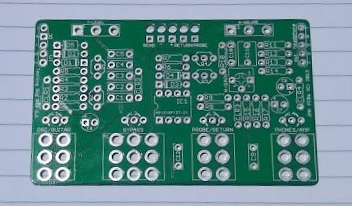
In the instance where this is a pedal built by Thermionic Studios, provide the specifics of the build in this section here. In the instance of a production pedal, either post an image of the completed PCB of the production in the enclosure, or remove this page section entirely.
| Item | Value |
|---|---|
| PCB Creator | (PCB Creator) |
| PCB Dimensions | length X width (metric) length x width (SAE) |
| Enclosure Size | Hammond 1590(!!)/1550(!!) |
| Enclosure Orientation | Portrait / Landscape |
| Power Adapter | 9 volts, Standard Boss "barrel-negative" supply 9-volt battery snap available |
| Power Consumption | 'XXX' milliamps |
Phase Inversion: No
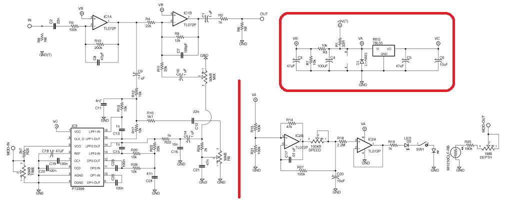
So the chart below may be a little bit confusing given a more complicated schematic. All that you really need to look at in the schematic is IC1. In the two opamps on IC1, when signal is sent through a "-" lead then the signal is amplified and inverted. So going through the first one inverts and then again through the second inverts again, "reverting" the signal back to the original phase.
IC2 never even touches the signal, it modifies the controls that touch the signal, but because IC2 doesn't touch the signal, it has no effect on the signal phase and therefore "N/A", or "not applicable".
| Schematic ID | Electronic Part | Action | Phase State |
|---|---|---|---|
| IC1a | TL072 | Inverts | Inverted |
| IC1b | TL072 | Inverts | Original |
| IC2a | TL072 | Does not Invert | N/A |
| IC2b | TL072 | Does not Invert | N/A |
That said, this is our best guess. Once built, we'll attach an oscilliscope and verify if the phase from the output is inverted from the input.
Schematic
For quite a while, we happened to believe that the 1776 Effects Build manual didn't appear to contain the schematic though there is a page for it. We reached out to 1776 effects and found that there was either something with our installation of Adobe Acrobat, or that 1776 did something quirky. Saving the build document to a proper .pdf file instead of browsing it from within Firefox(our preferred method) yields a schematic!
Artists
We are currently unaware of any artists actively using the pedal now, or who have in the past.
- Additional Sources

