Multiplex Echo Machine
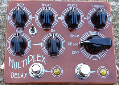
1776 Effects Multiplex Echo Machine. This is a delay pedal that appears to have been wholly designed and implemented by 1776 Effects. What makes this delay different from other delays available in the marketplace is that it enables emulation of three different magnetic tape-style echo/delays from days past:
- The Binson Echorec
- The Roland RE-201 Space Echo
- The Echoplex Ep3
This is done by using two different ICs (integrated circuits) and controlling the timing and order in which each IC has signal fed into it.
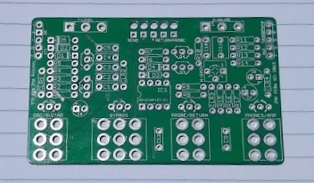
Thermionic Studios has purchased this PCB and sourced the parts necessary to build this pedal. We are in the process of building the pedal and will have more to report upon completion.
- Thermionic Studios has three(3) Multiplex Echo Machines
- One is "standard" with no modulation included,
- Another is a "single modboard" version which includes a 1776 Effects Echo mod-board, with the warble switchable between the echoes, and
- The final is a "double modboard" version which includes two 1776 Effects Echo mod-boards, one for each echo on the pedal.
- When we finish assembling them, they will be available for rental.
Controls
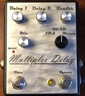
- Knob 1 - "Delay 1": Sets the delay time of the first delay - turning the knob clockwise increases the length of the delay.
- Knob 2 - "Delay 2": Sets the delay time of the second delay - turning the knob clockwise increases the length of the delay.
- Knob 3 - "Feedback": Increases / decreases the number of repeats - turning the knob clockwise increases the number of repeats.
- Knob 4 - "Mix": Adjusts the dry/wet blend. Align the knob directly in the middle to have a 50/50 dry/wet mix.
- Knob 5 (3-position switch) - "Tape Mode": Changes the way the signal is routed through the PT2399’s (the integrated circuits that do the actual delay calculations) to simulate tape delays of the past:
- Binson Echo rec
- Roland RE-201 Space Echo
- Echoplex v. Ep3
- Footswitch 1 - "Tape Speed": Holding down the momentary footswitch slowly speeds up the delay speed. Releasing the switch slows the speed back down to the time setting of the knob. The tape speed is highly interactive depending on how you have "Delay 2" set.
- Footswitch 2 -"On/Off": This turns the effect on and off in the signal chain
Please note that there are additional control instructions below, pertaining to the addition of a 1776 MP Modulation Board for the Multiplex Echo Machine.
Bypass: True
The Multiplex Echo Machine is a true bypass pedal.
General Information
PCB Modboards
The "MP Modulation Add-On PCB" is a small upgrade PCB made available by 1776 Effects and enables a builder to add a warble effect to a Multiplex Echo Machine PCB. With the addition of one of these PCBs, it is possible to create chorused, phased, or warbled sounds - sounds that emulate what would be created using those old original physical tape echo/delay systems. As it turns out, the aging, wearing, and eventual electronic drift of the components on the original units away from their specifications (or the actual stretching of the magnetic tape they employed), resulted in a "this-unit-needs-service"-type of modulation that in many cases ended up being preferred by musicians and listeners.
It's possible to hook up an MP Modulation Add-On PCB to either the first, or the second delay. If you're only adding one Mod PCB, 1776 Effects recommends installing the warble to the second delay. On the second image of the Multiplex Echo, notice the toggle that gives the user the ability to switch the warble between the first and second echoes.
Warble Controls
There are two knobs for each warble and the pair act as standard modulation controls:
- Speed Knob - "Speed": Sets the speed of the repeat of the warble modification of the echo effect. The period of the warble is made faster as the knob is turned clockwise.
- Depth Knob - "Depth": This control sets the eccentricity of the warble effect. Turning the knob clockwise will make the warble more extreme; counter-clockwise, less extreme.
- Here's the instruction from the 1776 Effects MP Modulation Board Build Guide
"To connect the modulation board to the Multiplex, wire the O (out) pad to lug 3 of the delay 2 pot on your Multiplex build. If you want to be able to turn off the mod connect a SPST or SPDT switch between the O (out) and Delay pot. You could also use an On/Off/On switch, connecting the O (out) to the center lug of the switch and connect one outer lug to Delay1 and the other outer lug to Delay2. This will turn off the modulation in the center position, or send it to either delay 1 or delay 2. If only wiring one delay pot you should choose delay pot 2."
http://1776effects.com/wp-content/uploads/2015/03/Multiplex-Build-Doc-1.7.pdf
Pedal Manual
As of this time, 1776effects.com has not issued a separate manual on how to use the pedal. The best current references that we're aware of are this wiki page, or the build manual linked here to the 1776 Effects website which describes the architecture of, and how to build the pedal.
Build Details
In the instance where this is a pedal built by Thermionic Studios, provide the specifics of the build in this section here. In the instance of a production pedal, either post an image of the completed PCB of the production in the enclosure, or remove this page section entirely.
| Item | Value |
|---|---|
| PCB Creator | (PCB Creator) |
| PCB Dimensions | length X width (metric) length x width (SAE) |
| Enclosure Size | Hammond 1590(!!)/1550(!!) |
| Enclosure Orientation | Portrait / Landscape |
| Power Adapter | 9 volts, Standard Boss "barrel-negative" supply 9-volt battery snap available |
| Power Consumption | 'XXX' milliamps |
Phase Inversion: No
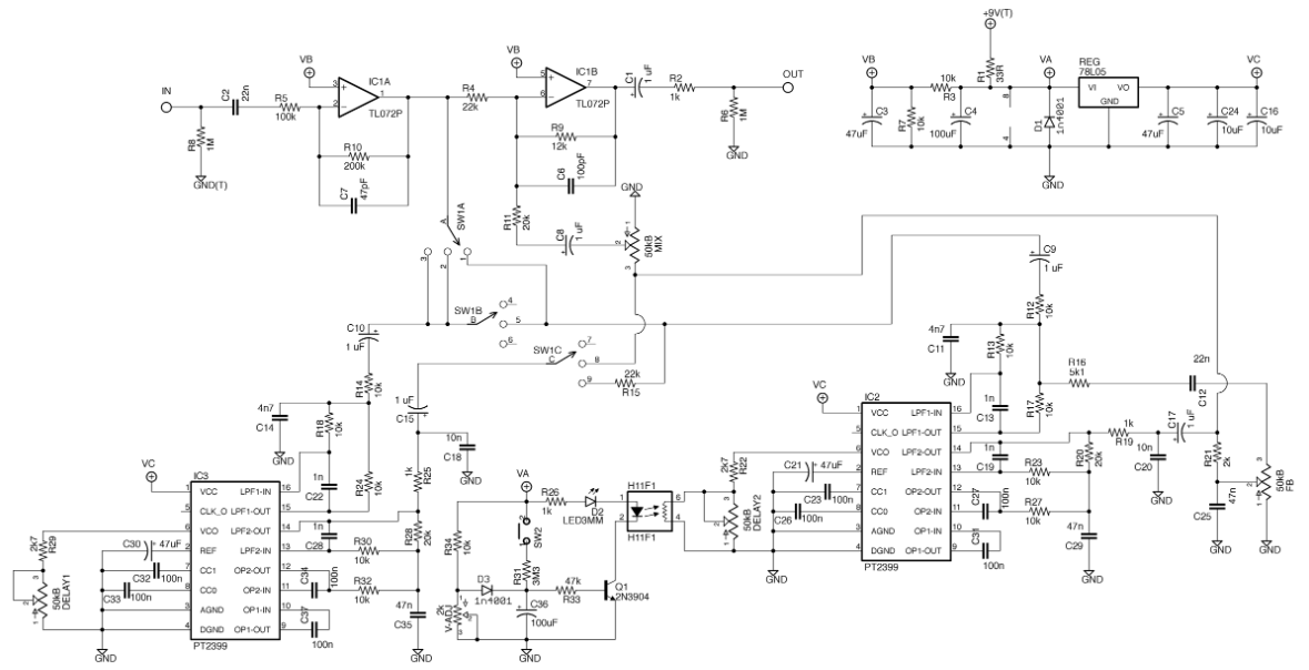
From our examination of the schematic below, the Multiplex Echo Machine appears to not invert phase on the output as compared with the signal that goes into the pedal.
Multiplex Echo
| Schematic ID | Electronic Part | Action | Phase State |
|---|---|---|---|
| IC1a | TL072 | Inverts | Inverted |
| IC1b | TL072 | Inverts | Reverted - back to Original |
| Q1 | 2N3904 | Inverts* | Unaffected - please see note |
- NOTE: Q1 modifies the period of the H11F1 IC. Q1 is engaged by means of the momentary switch (the Tape Speed control). So Q1 doesn't actually touch signal - just modifies the delay control. So while the transistor itself inverts phase, because it doesn't ever touch the signal, it can't cause a phase inversion of the signal coming out of the pedal.
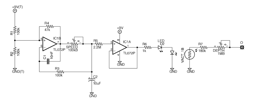
MP Modulation Board
| Schematic ID | Electronic Part | Action | Phase State |
|---|---|---|---|
| IC1a | TL072 | Non-inverting | Original |
| IC1b | TL072 | Non-inverting | Original |
As with all schematic observations, the phase state output by the pedal will need to be born out by testing of the actual pedal.
Schematic
Multiplex Echo
MP Modulation Board
Artists
We are currently unaware of any artists actively using the pedal now, or who have in the past.
- Additional Sources
