Difference between revisions of "DS-1"
(→Switching: Single Opamp) |
|||
| Line 42: | Line 42: | ||
* Later versions of the DS-1 using the dual op-amp invert phase. | * Later versions of the DS-1 using the dual op-amp invert phase. | ||
| − | ===Distortion | + | We're going to do this a little bit differently because we've never had to write up a pedal that in one incarnation kept phase, and in the other inverted phase. Here's to hoping that this format makes sense to most readers! |
| + | |||
| + | Truthfully, there's not that much difference between the two. It's probably the reason they sound so similar to each other. | ||
| + | |||
| + | ==Schematic 1: Made-in-Japan== | ||
| + | |||
| + | ===Distortion Circuit=== | ||
| + | |||
Here we list the the active components in the order which the schematic indicates the instrument signal flows through them. Even if you're not familiar with reading a schematic, you should be able to see, at a basic level, how the instrument signal flows through the circuit. | Here we list the the active components in the order which the schematic indicates the instrument signal flows through them. Even if you're not familiar with reading a schematic, you should be able to see, at a basic level, how the instrument signal flows through the circuit. | ||
| + | |||
{| class="wikitable" style="left; margin-right:20px; background-color:#eeffee;" cellpadding="10" | {| class="wikitable" style="left; margin-right:20px; background-color:#eeffee;" cellpadding="10" | ||
|- | |- | ||
| Line 59: | Line 67: | ||
|} | |} | ||
| − | ===Switching | + | ===Switching Circuit=== |
; Active Components: Q4: 2SC1685, Q5: 2SC1685, Q7: 2SK30A, Q8: 2SK30A | ; Active Components: Q4: 2SC1685, Q5: 2SC1685, Q7: 2SK30A, Q8: 2SK30A | ||
| Line 65: | Line 73: | ||
You'll probably notice that there are other active components in the schematic. We're not listing them because these components are part of the "popless" switching portion of the pedal. These components do not interact with any sound signal from an instrument. As a result, these parts don't have a meaningful effect in terms of inverting the signal's phase or changing or affecting the sound of the signal. | You'll probably notice that there are other active components in the schematic. We're not listing them because these components are part of the "popless" switching portion of the pedal. These components do not interact with any sound signal from an instrument. As a result, these parts don't have a meaningful effect in terms of inverting the signal's phase or changing or affecting the sound of the signal. | ||
| + | ===Single Op-Amp Schematic=== | ||
| − | -- | + | [[File:Boss_DS-1Schematic.png|center|frame|<div style="text-align:right">Assumed Public Domain; unaware of any Copyright claims by P. Schmidt.</div>]] |
| − | ===Distortion | + | ==Schematic 2: Post-Japan== |
| + | |||
| + | ===Distortion Circuit=== | ||
After review, we're surprised that the engineer who created the updated version 2 of the DS-1 didn't use either pin 2 on IC1A, or pin 6 on IC1B instead so as to properly invert the signal for a second time so as to make sure that a non-inverted signal would be coming out of the pedal. The simplest explanation is that the issue of phase inversion was not even a consideration. | After review, we're surprised that the engineer who created the updated version 2 of the DS-1 didn't use either pin 2 on IC1A, or pin 6 on IC1B instead so as to properly invert the signal for a second time so as to make sure that a non-inverted signal would be coming out of the pedal. The simplest explanation is that the issue of phase inversion was not even a consideration. | ||
| Line 91: | Line 102: | ||
|} | |} | ||
| − | ===Switching | + | ===Switching Circuit=== |
| + | |||
; Active Components: Q4: 2SC1685, Q5: 2SC1685, Q8: 2SK30A | ; Active Components: Q4: 2SC1685, Q5: 2SC1685, Q8: 2SK30A | ||
| Line 100: | Line 112: | ||
But when we considered the same notion for the clean tone (with the idea you don't want to go through more active components than you need to) we reversed ourselves. Since each active component has the possibility of coloring your tone, the place you'd want it minimized is in your clean, not your distorted tone. Once we considered this, we all came down on the side of the Post-Japan schematic, and the clean signal not going through Q7 as the more clever electronic design. | But when we considered the same notion for the clean tone (with the idea you don't want to go through more active components than you need to) we reversed ourselves. Since each active component has the possibility of coloring your tone, the place you'd want it minimized is in your clean, not your distorted tone. Once we considered this, we all came down on the side of the Post-Japan schematic, and the clean signal not going through Q7 as the more clever electronic design. | ||
| − | == | + | ===Dual Op-Amp Schematic=== |
| − | |||
| − | |||
| − | |||
| − | |||
| − | |||
[[File:Boss_DS-1Schematic2.png|center|frame|<div style="text-align:right">© Copyright 2008, Muhammad Iqbal</div>]] | [[File:Boss_DS-1Schematic2.png|center|frame|<div style="text-align:right">© Copyright 2008, Muhammad Iqbal</div>]] | ||
Revision as of 21:13, 1 July 2019
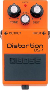
Boss DS-1 Distortion. Including the ProCo Rat, and the Electro Harmonix Big Muff Pi, this pedal has become renown for having earned the hearts of not only aspiring rock stars, but also for well-seasoned studio musicians and celebrity professionals.
The Boss DS-1 has gone through a couple of incarnations: the older and more highly-esteemed Made-in-Japan model, and the less-valued post-Japan model. Candidly, we don't really hear much of a difference, if any at all. After listening to a shoot-out between new and old models, many actually hear the newer DS-1 as "thicker" or "meatier" and like it better than the vintage model. We have a convenient link below for you to listen yourself.
We have an MIJ-version DS-1. Why do we have an MIJ DS-1? Not because we were on the look-out for one, but because one day we happened to see one at a Goodwill store. It was practically mint condition and the right price so we decided, "why not?"
- Thermionic Studios has one(1) Boss black-label (Made-in-Japan) DS-1 available for rental.
Controls

- Knob 1 - "Tone": Adjusts the Tone with fully clockwise allowing all the high-frequency tone information into the signal.
- Knob 2 - "Level": Adjusts the output level with fully clockwise full loudness.
- Knob 3 - "Dist": Adjusts the distortion level with fully clockwise being maximum distortion.
- Footswitch 1 - "On/Off": This footswitch toggles the pedal between engaged/active ("On"), and bypassed ("Off")
Bypass: Buffered
The DS-1, like all Boss pedals, has a buffered bypass.
General Information
First offered for sale in 1978, the DS-1 Distortion was a follow-up to the Red-Yellow-Green pedal "marketing release" of the Boss SP-1 Spectrum (red), the OD-1 Overdrive (yellow), and the PH-1 Phaser (green).
Originally, the DS-1 was well received and today it continues to be a consistent, if much cheaper, seller for Boss. By contrast, none of the originally-conceived red-yellow-green pedals are even made or sold any longer. The SP-1 was killed off; and the OD-1 and PH-1 have been re-imagined into new pedals by Boss.
We have posted both versions of the schematics and the Owner's Manuals of the DS-1:
- The Made-in-Japan version
- The "Subsequent" version
Post-Japan Manufacturing
Once Boss stopped making pedals in Japan and transitioned over to manufacturing in Taiwan, the architecture of the electronics changed. Most notably, a dual-opamp was used in place of the original single TA7136. Of course, other changes were made in resistors and capacitors in the effort to make the pedal sound the same. We think Boss did a pretty good job.
So, we're fairly agnostic with respect to the sound of a modern DS-1 as compared to a vintage DS-1. We don't hear much of a difference, if any at all. If we were forced to offer an opinion on which pedal sounds "better", in our estimation, we'd probably say that we think they sound the same, with perhaps the newer version sounding just a touch "thicker".
Pedal Manual(s)
Phase Inversion: It Depends!
- The Made-in-Japan version of the DS-1 does not invert phase.
- Later versions of the DS-1 using the dual op-amp invert phase.
We're going to do this a little bit differently because we've never had to write up a pedal that in one incarnation kept phase, and in the other inverted phase. Here's to hoping that this format makes sense to most readers!
Truthfully, there's not that much difference between the two. It's probably the reason they sound so similar to each other.
Schematic 1: Made-in-Japan
Distortion Circuit
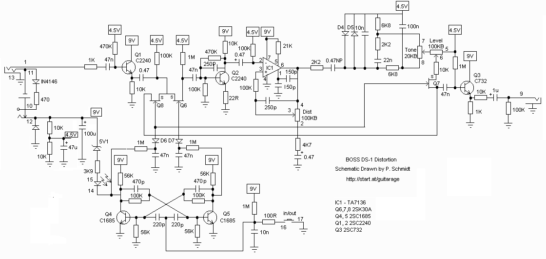
Here we list the the active components in the order which the schematic indicates the instrument signal flows through them. Even if you're not familiar with reading a schematic, you should be able to see, at a basic level, how the instrument signal flows through the circuit.
| Schematic ID | Electronic Part | Action | Phase State |
|---|---|---|---|
| Q1 | 2SC2240 | Does not Invert | Original |
| Q6 | 2SK30A | Does not Invert | Original |
| Q2 | 2SC2240 | Inverts | Inverted |
| IC1 | TA7136 | Inverts | Reverted |
| Q3 | 2SC732 | Does not Invert | Reverted |
Switching Circuit
- Active Components
- Q4: 2SC1685, Q5: 2SC1685, Q7: 2SK30A, Q8: 2SK30A
You'll probably notice that there are other active components in the schematic. We're not listing them because these components are part of the "popless" switching portion of the pedal. These components do not interact with any sound signal from an instrument. As a result, these parts don't have a meaningful effect in terms of inverting the signal's phase or changing or affecting the sound of the signal.
Single Op-Amp Schematic
Schematic 2: Post-Japan
Distortion Circuit
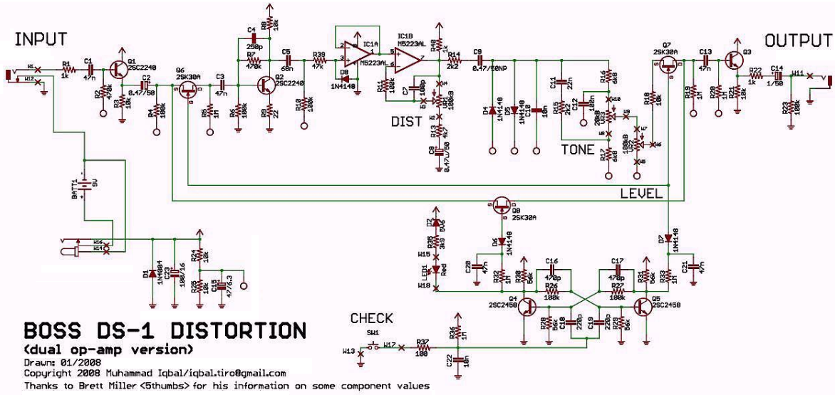
After review, we're surprised that the engineer who created the updated version 2 of the DS-1 didn't use either pin 2 on IC1A, or pin 6 on IC1B instead so as to properly invert the signal for a second time so as to make sure that a non-inverted signal would be coming out of the pedal. The simplest explanation is that the issue of phase inversion was not even a consideration.
| Schematic ID | Electronic Part | Action | Phase State |
|---|---|---|---|
| Q1 | 2SC2240 | Does not Invert | Original |
| Q6 | 2SK30A | Does not Invert | Original |
| Q2 | 2SC2240 | Inverts | Inverted |
| IC1A | M5223AL | Does not Invert | Inverted |
| IC1B | M5223AL | Does not Invert | Inverted |
| Q7 | 2SK30A | Does not Invert | Inverted |
| Q3 | 2SC732 | Does not Invert | Inverted |
Switching Circuit
- Active Components
- Q4: 2SC1685, Q5: 2SC1685, Q8: 2SK30A
The main differences between the switching of the later version of the DS-1 and the MIJ is the manner of Q7 acting as a switch for turning the distortion effect on and off.
We were going back and forth on this, and at first we thought that perhaps the more clever electronic design was on the Made-in-Japan schematic with the distorted signal NOT going through Q7. This would then, in theory, give a "purer" distortion tone. In audio amplification / effects, you typically don't want to go through more active components than you need to.
But when we considered the same notion for the clean tone (with the idea you don't want to go through more active components than you need to) we reversed ourselves. Since each active component has the possibility of coloring your tone, the place you'd want it minimized is in your clean, not your distorted tone. Once we considered this, we all came down on the side of the Post-Japan schematic, and the clean signal not going through Q7 as the more clever electronic design.
Dual Op-Amp Schematic
Artists
We are currently unaware of any artists actively using the pedal now, or who have in the past.
- Additional Sources
- https://www.diystompboxes.com/DIYFiles/up/Build_Your_Own_DS-1_Distortion.pdf
- https://www.youtube.com/watch?v=RhTxcfcT9fU - Listen for yourself to see if there's a big difference...

