Difference between revisions of "Cardinal Tremolo"
m (→Bypass:True) |
(→Artists) |
||
| (2 intermediate revisions by the same user not shown) | |||
| Line 15: | Line 15: | ||
Thermionic Studios purchased this PCB from 1776 and sourced the parts necessary to build this pedal. We are in the process of building the pedal and will have more to report upon completion. | Thermionic Studios purchased this PCB from 1776 and sourced the parts necessary to build this pedal. We are in the process of building the pedal and will have more to report upon completion. | ||
| − | + | ||
| + | ; Thermionic Studios has one(1) Harmonic Tremolo. When we finish assembling it, it will be available for rental. | ||
==Controls== | ==Controls== | ||
| Line 52: | Line 53: | ||
==Pedal Manual== | ==Pedal Manual== | ||
As of this time, 1776effects.com has not issued a separate manual on how to use the pedal. The best current references that we're aware of are this wiki page, or the build manual linked here to the 1776 Effects website which describes the architecture of, and how to build the pedal. | As of this time, 1776effects.com has not issued a separate manual on how to use the pedal. The best current references that we're aware of are this wiki page, or the build manual linked here to the 1776 Effects website which describes the architecture of, and how to build the pedal. | ||
| + | |||
| + | ==Build Details== | ||
| + | In the instance where this is a pedal built by Thermionic Studios, provide the specifics of the build in this section here. In the instance of a production pedal, either post an image of the completed PCB of the production in the enclosure, or remove this page section entirely. | ||
| + | |||
| + | [[File:JMKPCBs_TestingRig_PCB.png|center|frame|<div style="text-align:right">JMKPCBs Testing Rig PCB</div>]] | ||
| + | |||
| + | <center> | ||
| + | {| class="wikitable" style="center; margin-right:20px; background-color:#eeffee;" cellpadding="10" | ||
| + | |- | ||
| + | ! Item || Value | ||
| + | |- | ||
| + | | '''''PCB Creator''''' || (PCB Creator) | ||
| + | |- | ||
| + | | PCB Dimensions || length X width (metric)<br>length x width (SAE) | ||
| + | |- | ||
| + | | Enclosure Size || Hammond 1590(!!)/1550(!!) | ||
| + | |- | ||
| + | | Enclosure Orientation || Portrait / Landscape | ||
| + | |- | ||
| + | | Power Adapter || 9 volts, Standard Boss "barrel-negative" supply <br>9-volt battery snap available | ||
| + | |- | ||
| + | | Power Consumption || 'XXX' milliamps | ||
| + | |} | ||
| + | </center> | ||
==Phase Inversion: No== | ==Phase Inversion: No== | ||
| Line 92: | Line 117: | ||
;Additional Sources | ;Additional Sources | ||
* [http://1776effects.com/wp-content/uploads/2015/12/Cardinal-Trem-V2.pdf Build Instructions Cardinal Tremolo, v.2] | * [http://1776effects.com/wp-content/uploads/2015/12/Cardinal-Trem-V2.pdf Build Instructions Cardinal Tremolo, v.2] | ||
| + | * [https://www.youtube.com/watch?v=3c83-tmsoqs Cardinal Tremolo Bias and Balance YouTube Instructions] | ||
Latest revision as of 23:51, 9 January 2023
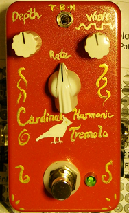
The 1776 Effects Cardinal Tremolo v1 is a tremolo effect pedal evocative of a particular kind of tremolo effect called the "Harmonic Tremolo" that was available from certain Fender amps, from 1960 to 1963. Fender didn't use the term, "Harmonic Tremolo". We believe this is the term that Jon Patton, the tinkerer of this circuit, applied.
These amps include:
- The Fender Concert,
- The Fender Pro,
- The Fender Showman,
- The Fender Super, and
- The Fender Twin
The nature of the Harmonic Tremolo and its difference from a standard tremolo effect seems to be that the harmonic tremolo (as designed by Fender) implements two different modulations of tremolo, each interacting with the other to create a tremolo sound that's not like a standard single sine-wave control of a tremolo. This is effected in the corresponding Fender amplifiers by using 2 triodes (a full single 12ax7 tube). For the purposes of comparison and education, here's a link to the Fender Showman amp page that has a corresponding schematic (the early 1960s, or the "6G14" circuit).
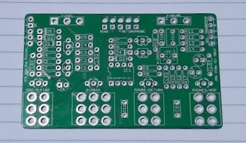
Thermionic Studios purchased this PCB from 1776 and sourced the parts necessary to build this pedal. We are in the process of building the pedal and will have more to report upon completion.
- Thermionic Studios has one(1) Harmonic Tremolo. When we finish assembling it, it will be available for rental.
Controls

- Knob 1 - "Depth": Sets the depth of the volume swell of the tremolo. Clockwise turning increases the depth of the swell.
- Knob 2 - "Rate": Sets the speed of the swell of the tremolo. Clockwise turning increases the rapidity of the period of the swell.
- Switch 1 - "Select": Allows selection between Harmonic and Standard Tremolo functions.
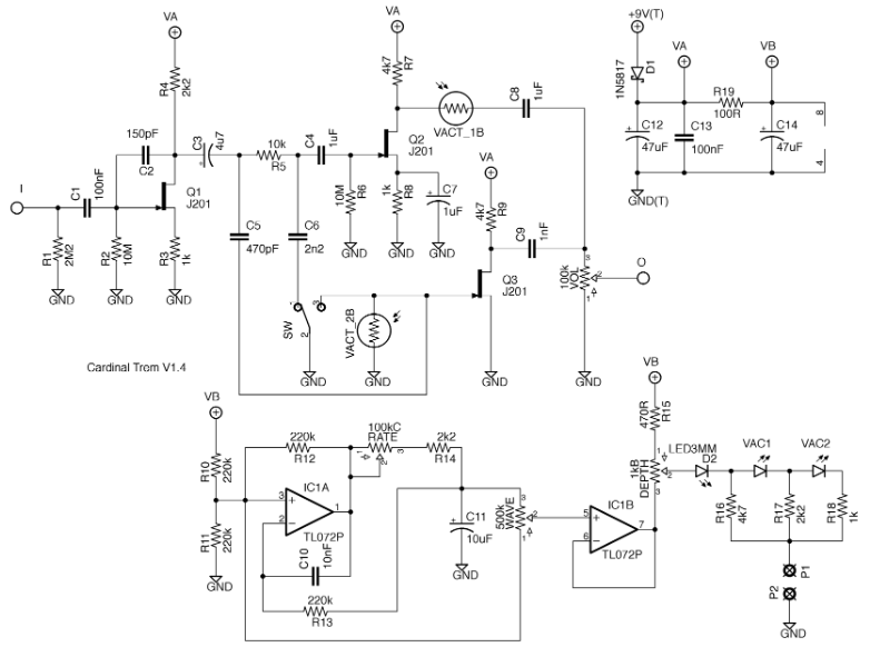
If you look at the schematic, you'll notice that the "Rate", "Wave", and "Depth" controls are hooked up to the ICs in the portion of the circuit that actually doesn't touch the signal. Our earlier version of this pedal has the "Wave" and "Volume" controls set by trimmer resistors on the PCB. The later version of this PCB makes these controls available on the face of the pedal. The volume is also set by a trimmer control, and we've set it to "unity gain" so that there's no discernable difference between the output of the pedal whether it is engaged, or disengaged.
The electronic functioning of this portion is discussed in greater depth under the "Phase Inversion" section.
Bypass: True
The Cardinal Tremolo is a true bypass pedal.
General Information
The Cardinal Tremolo makes available both the amplike "Harmonic" tremolo, as well as a standard volume-swell tremolo effect.
http://1776effects.com/wp-content/uploads/2015/03/Cardinal-Tremolo.pdf
We currently only have Version 1 of the Cardinal Tremolo pcb.
1776 Effects has also released a Version 2. A quick look the schematics of both v1 and v2 suggests that the only meaningful difference between the two is that the Version 2 board takes what are trimpots (set-em and forget-em) on what are Version 1's printed circuit board and exposes them as full potentiometers.
Per the build notes document, this is a circuit by Jon Patton that was extensively influenced by previous tremolo pedal designs. In the build notes, Jon credits:
This circuit is based in part on RG Keen's Pro-Vibrato schematic. The LFO was adapted from CultureJam's Shoot the Moon Tremolo, which in turn adapted from Dann Green's Tremulus Lune. Thanks to Jimi Photon for the inspiration and samhay, ~arph, and duck_arse for discussions and suggestions on DIYStompboxes.
From an examination of the schematic, it appears that the switch that toggles between the harmonic tremolo and the standard tremolo does so by either including or excluding the second vactrol.
Pedal Manual
As of this time, 1776effects.com has not issued a separate manual on how to use the pedal. The best current references that we're aware of are this wiki page, or the build manual linked here to the 1776 Effects website which describes the architecture of, and how to build the pedal.
Build Details
In the instance where this is a pedal built by Thermionic Studios, provide the specifics of the build in this section here. In the instance of a production pedal, either post an image of the completed PCB of the production in the enclosure, or remove this page section entirely.
| Item | Value |
|---|---|
| PCB Creator | (PCB Creator) |
| PCB Dimensions | length X width (metric) length x width (SAE) |
| Enclosure Size | Hammond 1590(!!)/1550(!!) |
| Enclosure Orientation | Portrait / Landscape |
| Power Adapter | 9 volts, Standard Boss "barrel-negative" supply 9-volt battery snap available |
| Power Consumption | 'XXX' milliamps |
Phase Inversion: No
From our examination of the schematic below, the Cardinal Tremolo, v1 appears to not invert phase on the output as compared with the signal that goes into the pedal.
| Schematic ID | Electronic Part | Action | Phase State |
|---|---|---|---|
| Q1 | J201 | Inverts | Inverted |
| Q2* | J201 | Inverts | Reverted - see note 1 |
| Q3 | J201 | Inverts | Reverted |
| IC1a* | TL072 | Does not Invert | Unaffected - see note 2 |
| IC1b | TL072 | Does not Invert | Unaffected |
- NOTE 1: The signal is split after passing through Q1 going through both Q2 and Q3. However, signal that goes through Q2 does not go through Q3. Similarly, signal that goes through Q3 does not go through Q2. Both Q2 and Q3 invert phase, so that when the signals combine again after having passed through Q2 or Q3, they still have the same phase. Phase is inverted at Q1, and then reverted at either Q2 or Q3 back to the original phase.
- NOTE 2: IC1 doesn't appear to invert the sound signal phase through either portion of the integrated circuit. IC1 is used to modify how the speed and depth controls affect the sound signal, but the current going through IC1 never touches the audio signal.
As with all schematic observations, this will need to be born out by testing of the actual pedal.
Regarding the separation of the "Rate", "Wave", and "Depth" controls from the rest of the portion of the circuit that modifies the signal: A vactrol (also called a "Resistive Opto-Isolator") is an electronic component, the combination of which is a light-emitting diode (LED), and a light-sensitive resistor. When light from the LED hits the resistor, the resistance in the resistor drops.
On the part of the circuit where you find diode symbols labeled "Vac1", and "Vac2", that portion of the circuit controls the pulsation of the light through the LEDs. On the other portion of the circuit, bounded by the labels "I" (for input), and "O", is where the signal passes through. The other halves of the vactrols (the resistive portions) are labeled "Vact_1B" and "Vact_2B" and their resistances change (allowing more or less signal through) per the pulsing of the LEDs. The switch engages/disengages the second vactrol, alternating the function of the pedal between a "harmonic" and "standard" tremolo.
Schematic
Artists
We are currently unaware of any artists actively using the pedal now, or who have in the past.
- Additional Sources

