Difference between revisions of "BF-2"
(→Schematic) |
(→Phase Inversion:Yes/No) |
||
| Line 22: | Line 22: | ||
| − | ==Phase Inversion: | + | ==Phase Inversion:Unknown== |
| + | This is a rather unusual schematic. Instead of putting the correct symbol in the schematic for the modulation ICs, they've just drawn actual ICs. We also can't tell the electrical polarity of the ICs that are opamps because "2" and "3", and "6" and "5" are not indicative. We'll have to go looking for the opamps to better understand. To the best of our knowledge, most, but not all opamps have negative on pins 2 and 6, and positive on 3, and 5, but not always. As with other pedals, we'll have to put this on an oscilloscope to make sure whether it inverts phase or not. | ||
| + | |||
{| class="wikitable" style="left; margin-right:20px; background-color:#eeffee;" cellpadding="10" | {| class="wikitable" style="left; margin-right:20px; background-color:#eeffee;" cellpadding="10" | ||
|- | |- | ||
! Schematic ID || Electronic Part || Action || Phase State | ! Schematic ID || Electronic Part || Action || Phase State | ||
|- | |- | ||
| − | | X || X || X || X | + | | Q1 || X || X || X |
| + | |- | ||
| + | | IC1b || X || X || X | ||
| + | |- | ||
| + | | IC2b || X || X || X | ||
| + | |- | ||
| + | | Q2 || X || X || X | ||
| + | |- | ||
| + | | IC3 || X || X || X | ||
| + | |- | ||
| + | | IC4 || X || X || X | ||
| + | |- | ||
| + | | Q3 || X || X || X | ||
| + | |- | ||
| + | | IC2a || X || X || X | ||
| + | |- | ||
| + | | Q4 || X || X || X | ||
| + | |- | ||
| + | | IC1a || X || X || X | ||
|} | |} | ||
| + | |||
| + | On the schematic there are additional opamps and transistors, but they're dealing with modulation and power, not with sound, and so do not directly affect the signal in the pedal. | ||
==Schematic== | ==Schematic== | ||
Revision as of 02:42, 10 April 2018
Boss BF-2 Flanger. "The purple one."
Controls
- Knob 1 - "Manual":
- Knob 2 - "Depth":
- Knob 3 - "Rate":
- Knob 4 - "Res": (Resonance)
- Footswitch 1 - "On/Off": This switch toggle the pedal effect off and on.
Bypass:Buffered/True
Like all Boss pedals, the BF-2 Flanger has a buffered bypass.
General Information
Pedal Manual
Phase Inversion:Unknown
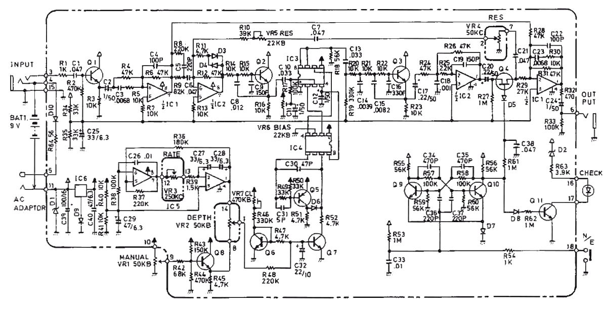
This is a rather unusual schematic. Instead of putting the correct symbol in the schematic for the modulation ICs, they've just drawn actual ICs. We also can't tell the electrical polarity of the ICs that are opamps because "2" and "3", and "6" and "5" are not indicative. We'll have to go looking for the opamps to better understand. To the best of our knowledge, most, but not all opamps have negative on pins 2 and 6, and positive on 3, and 5, but not always. As with other pedals, we'll have to put this on an oscilloscope to make sure whether it inverts phase or not.
| Schematic ID | Electronic Part | Action | Phase State |
|---|---|---|---|
| Q1 | X | X | X |
| IC1b | X | X | X |
| IC2b | X | X | X |
| Q2 | X | X | X |
| IC3 | X | X | X |
| IC4 | X | X | X |
| Q3 | X | X | X |
| IC2a | X | X | X |
| Q4 | X | X | X |
| IC1a | X | X | X |
On the schematic there are additional opamps and transistors, but they're dealing with modulation and power, not with sound, and so do not directly affect the signal in the pedal.
Schematic
Artists
- Additional Sources

